



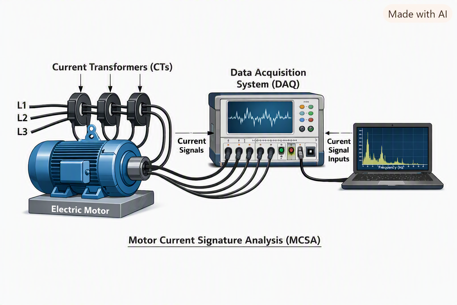
Induction motors are the workhorses of modern industry, consuming approximately 69% of industrial power and 29% of total global power generation . Their reliable operation is critical to production, yet failures remain a persistent challenge, with maintenance expenditure accounting for up to 80% of a motor’s total lifecycle cost. This article explores the common failure modes of induction motors and provides a comprehensive guide to predictive maintenance strategies, leveraging advanced diagnostic techniques to prevent downtime and extend equipment life.
Understanding the High Cost of Motor Failures
The financial impact of motor failures extends far beyond the cost of replacement or repair. Unplanned downtime, production losses, and safety risks can be devastating. According to the Electric Power Research Institute, inter-turn short-circuit faults alone contribute approximately 37% of induction motor failures. Stator winding faults account for 30-40% of overall motor failures, while approximately 80% of power circuit-related failures stem from poor connections or high-resistance-connection (HRC) faults.
Organizations relying on reactive maintenance—addressing problems only after failure occurs—face extended downtime and diminished productivity. In contrast, a well-structured predictive maintenance program leverages data to anticipate failures and schedule interventions precisely when needed, minimizing both downtime and unnecessary maintenance costs.
Common Failure Modes in Induction Motors
Understanding how and why induction motors fail is the first step toward prevention. Failures typically originate from three main component categories: the stator windings, the rotor assembly, and the bearing systems.
Stator Winding Failures
Stator windings are among the most failure-prone components. Insulation breakdown is the primary culprit, driven by a combination of stresses:
- Thermal Stress: Overheating accelerates insulation aging and degradation. Operating a motor beyond its thermal limits, even for short periods, progressively weakens the dielectric strength of the insulation system.
- Electrical Stress: Voltage spikes, transients, and harmonics—often introduced by variable-frequency drives (VFDs)—can cause partial discharge and insulation pinholes.
- Mechanical Stress: Coil movement from electromagnetic forces and rotor strikes can physically damage insulation.
- Environmental Stress: Moisture, chemical contamination, and abrasion degrade insulation properties over time.
Turn-to-turn faults, phase-to-ground faults, and open circuits are common outcomes of insulation degradation.
Rotor and Squirrel-Cage Failures
The rotor, typically of squirrel-cage construction, is susceptible to:
- Broken Rotor Bars: Caused by thermal cycling, mechanical stress, or manufacturing defects, cracked bars create asymmetries in the rotor’s magnetic field.
- Rotor Eccentricity: Uneven air gap between rotor and stator, resulting from bearing wear or shaft misalignment, causes unbalanced magnetic pull and increased vibration.
- Rotor Deformation: Mechanical damage or excessive centrifugal forces can distort the rotor structure.
Bearing Failures
Bearing faults are a leading cause of induction motor failure, often arising from:
- Lubrication Issues: Under-lubrication, over-lubrication, or contamination of lubricant accelerates bearing wear.
- Electrical Currents: Shaft currents from VFDs or electrostatic coupling can cause electrical pitting and fluting on bearing surfaces.
- Mechanical Stresses: Imbalance, misalignment, and excessive axial or radial loads shorten bearing life.
Predictive Maintenance: A Proactive Strategy
Predictive maintenance (PdM) uses real-time data from sensors and advanced analytics to identify developing faults before they cause failure . Unlike preventive maintenance, which follows a fixed schedule, PdM is condition-based, enabling maintenance to be performed exactly when needed.
Motor Current Signature Analysis (MCSA)
Motor Current Signature Analysis is a powerful, non-invasive technique that monitors the electrical current flowing to the motor . Since the motor acts as a transducer, its current draw reflects both electrical and mechanical load variations.
MCSA can detect: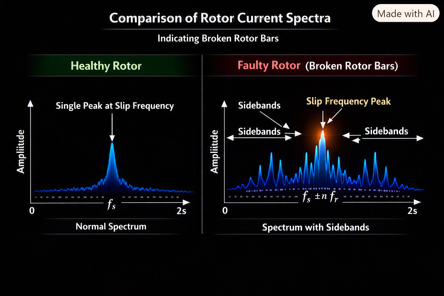
- Broken Rotor Bars: Sidebands around the supply frequency indicate rotor asymmetries.
- Bearing Faults: Characteristic frequency components in the current spectrum reveal incipient bearing wear.
- Air Gap Eccentricity: Unbalanced magnetic pull generates distinctive current signatures.
- Misalignment: Asymmetric loading manifests in the current spectrum.
For VFD-fed motors, conventional MCSA requires careful interpretation due to drive harmonics. Mode-based voltage and current systems may offer more reliable analysis in these applications.
Vibration Analysis
Vibration analysis is a cornerstone of mechanical condition monitoring. By measuring vibration at specific points on the motor, analysts can identify: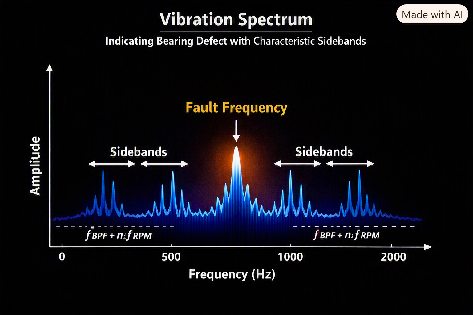
- Imbalance: Characteristic fundamental frequency vibration.
- Misalignment: Axial and radial vibration at multiples of rotational speed.
- Bearing Defects: Distinct frequency signatures from damaged rolling elements .
- Looseness: Non-linear vibration patterns.
Infrared Thermography
Thermal imaging is a complementary diagnostic technique that detects overheating in motor components. Using automated methodology based on ASTM E1934-99a, infrared analysis can identify: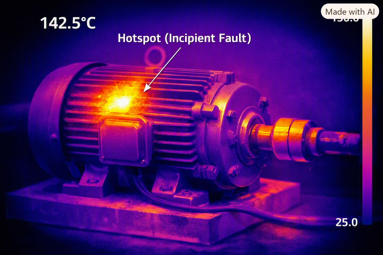
- Hot spots in windings, suggesting insulation degradation.
- Overheating bearings, indicating lubrication failure or excessive load.
- Blocked cooling passages or restricted ventilation.
- Loose electrical connections in terminal boxes.
This technique can be integrated with automated image segmentation to enable continuous thermal monitoring.
Digital Twin Technology
Digital twins are virtual replicas of physical motors, integrating multi-sensor data—current, voltage, vibration, and temperature—with physics-based models and machine learning algorithms.
Key applications include:
- Condition Monitoring: Continuous assessment of motor health.
- Fault Diagnosis: Early detection of bearing wear, rotor bar cracks, and stator winding faults.
- Remaining Useful Life (RUL) Estimation: Predicting time-to-failure to optimize maintenance scheduling.
Advanced Predictive Technologies
Emerging technologies are pushing the boundaries of fault detection and predictive analytics:
Machine Learning and AI
Supervised learning algorithms, including Support Vector Machines and Random Forest classifiers, are increasingly used to classify fault types from vibration and current data. Time-domain features such as waveform length, zero-crossing count, and slope sign changes have demonstrated high effectiveness in identifying bearing faults, with classification accuracies exceeding 99% in some studies.
Self-Supervised and Federated Learning
Recent innovations in self-supervised and federated learning enable robust fault detection under noisy conditions and across multiple industrial sites without sharing proprietary data. These approaches achieve high accuracy even at low signal-to-noise ratios, delivering significant improvements over conventional deep learning baselines.
Implementing an Effective PdM Program
1. Establish a Baseline
When commissioning a new motor, collect baseline data—MCSA spectra, vibration signatures, thermal profiles, and insulation resistance values. These data points become your reference for future trending.
2. Select the Right Monitoring Techniques
Criticality and operating environment should dictate the monitoring approach:
- High-criticality motors: Combine MCSA, vibration analysis, and thermography for comprehensive coverage.
- VFD-fed motors: Employ specialized techniques such as mode-based voltage and current analysis.
- Motors in hazardous areas: Prioritize non-intrusive methods like MCSA.
3. Train Personnel and Establish Clear Roles
Successful PdM requires skilled personnel in three key roles:
- Operators who can correctly and consistently collect measurement data.
- Interpreters who can identify predefined defects and signatures.
- Analysts who understand the underlying principles, interpret complex data, and provide risk-based recommendations.
4. Trend Data and Track Performance
Maintain a library of results to identify subtle changes over time. MCSA data, for example, should be trended to detect increasing fault signals, which may indicate progressing damage.
5. Integrate with CMMS
Link predictive data with your Computerized Maintenance Management System (CMMS) to automate work order generation, spare parts planning, and maintenance scheduling.
The Cost-Benefit Equation
While implementing predictive maintenance requires upfront investment in sensors, software, and training, the returns are substantial. By shifting from reactive to predictive strategies, organizations can;
- Reduce unplanned downtime by up to 50%.
- Extend motor service life.
- Optimize spare parts inventory.
- Improve workplace safety by identifying hazards early.
- Lower energy consumption through improved efficiency.
A key consideration is avoiding false positives—unnecessary corrective actions that increase costs without providing benefit. Predictive systems should be calibrated to balance sensitivity and specificity.
Conclusion
Induction motor failures are a major source of operational disruption, but they are not inevitable. By understanding the common failure modes—stator winding degradation, rotor defects, and bearing wear—and implementing a robust predictive maintenance program incorporating MCSA, vibration analysis, thermography, and emerging digital twin technologies, organizations can dramatically improve reliability, reduce costs, and extend equipment life.
The transition from reactive to predictive maintenance requires investment in technology, training, and cultural change. However, for industries where every hour of production counts, the return on investment makes this one of the most valuable strategies available.