



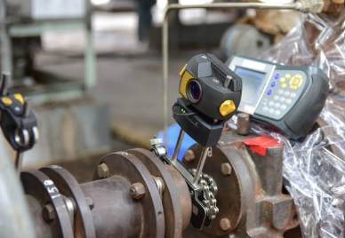
Laser shaft alignment is the modern standard for ensuring rotating equipment runs smoothly and reliably. Misalignment is a leading cause of premature bearing wear, seal failures, and excessive energy consumption. This guide walks you through the complete process from preparation and soft foot correction to data collection and final verification using laser alignment technology. You will learn the key terminology, tolerances, and best practices that maintenance professionals use to extend machine life and reduce downtime.
1. Why Shaft Alignment Matters
Rotating machinery—pumps, motors, gearboxes, and compressors—relies on properly aligned shafts to transfer power efficiently. When shafts are misaligned, the coupling is forced to compensate, creating stress that radiates through the entire drivetrain. This stress manifests as vibration, heat, and accelerated wear on bearings, seals, and couplings.
The consequences of misalignment are both mechanical and financial. A mere 0.015-inch gap at 3,000 RPM can increase power consumption by nearly 4% per motor. Across dozens of machines, this translates into thousands of dollars in wasted electricity each year. Bearings and seals fail at three to four times their expected lifespan, causing costly unplanned downtime during peak production runs.
Precision alignment directly impacts uptime, energy efficiency, and overall machine longevity. Documented benefits include up to 7% reduction in maintenance costs, up to 8x longer bearing and seal life, and 5% to 12% reduction in energy costs.
2. Understanding Misalignment: Offset and Angularity
Shaft misalignment exists in two primary forms:
- Offset (parallel misalignment): The centerlines of the two shafts are parallel but not collinear. One shaft is shifted laterally relative to the other.
- Angular misalignment (gap): The centerlines of the two shafts meet at an angle rather than being parallel.
Most real-world misalignment is a combination of both. Laser alignment systems measure and correct both simultaneously.
The precision required depends on shaft speed and coupling type. General guidelines for acceptable maximum misalignment when manufacturer specifications are unavailable:
| RPM Range | Angularity (mm/100mm) | Offset (mm) |
| 0–1,000 | 0.1 | 0.13 |
| 1,000–2,000 | 0.08 | 0.1 |
| 2,000–3,000 | 0.07 | 0.07 |
| 3,000–4,000 | 0.06 | 0.05 |
| 4,000–6,000 | 0.05 | 0.03 |
Note: Always prioritize the equipment manufacturer’s specifications over general tables.
3. Laser Alignment vs. Traditional Methods
Traditional Dial Indicator Methods
Before laser systems, technicians used dial indicators with methods such as the reverse indicator method (also called the double dial method) and the face and rim method. These techniques measure shaft positions using mechanical gauges and require manual calculations or graph paper plotting.
The reverse indicator method, developed in the mid-to-late 1950s, measures from both shaft centerlines rather than the coupling surface, which eliminates concern about coupling machining quality. However, dial indicator methods suffer from bracket sag, reading errors, and the need for extensive manual calculations.
Why Laser Alignment Wins
Laser shaft alignment systems have become the preferred solution because they eliminate the inherent limitations of dial indicators:
- 20x higher measurement resolution for pinpoint accuracy
- 60–70% faster alignments compared to dial indicators
- Automatic calculations—no manual math or graph paper
- Hundreds of data points captured in seconds, versus just 3–4 with dial indicators
- No indicator bracket sag—eliminates a major source of measurement error
- Live Move Data—real-time feedback during adjustments
- Professional reports—color-printed documentation for maintenance audits
Modern systems use inclinometers in each sensor unit to detect rotational orientation, enabling precise measurement even when shafts are uncoupled.
4. Pre-Alignment Preparation
Soft Foot Inspection
Soft foot is one of the most common and damaging alignment problems. It occurs when one or more machine feet do not sit flat on the baseplate, causing the machine frame to distort when bolts are tightened. This distortion changes shaft position and defeats even the most careful alignment work.
To check for soft foot, loosen each hold-down bolt one at a time while monitoring shaft movement with a dial indicator or the laser system itself. If the shaft moves more than 0.002–0.003 inches when a bolt is loosened, soft foot is present. Correct it by adding shims under the affected foot or by machining the foot surface as needed.
Foundation and Bolt Condition
Before starting alignment, verify that the foundation is rigid, all hold-down bolts are in good condition, and shim packs are clean and properly stacked. Any instability between the machine feet and base will cause each shaft to move differently once rotation begins, introducing misalignment errors from the start.
Thermal Growth Considerations
Machines that operate at high temperatures—steam turbines, hot pumps, and compressors grow as they heat up. A machine that is perfectly aligned when cold may be severely misaligned when hot. Thermal growth values must be known as specifications in the shaft alignment setup.
Research on a 3 MW steam turbine found that thermal growth caused alignment differences of 1.0 thous (gap) and 2.8 thous (offset) in the vertical plane between hot and cold conditions. Laser alignment systems allow you to enter thermal expansion data so the alignment targets in cold condition are compensated to achieve perfect alignment during operation.
5. Step-by-Step Laser Alignment Procedure
Step 1: Mount the Laser and Sensor Units
Attach the laser transmitter and sensor (receiver) units to the shafts on either side of the coupling using mounting brackets. The brackets must provide sufficient precision—if shafts must be aligned to within 16 arcseconds, the base-to-shaft alignment precision should be reproducible to within 4 arcseconds or better.
For couplings with gear teeth or non-smooth surfaces, brackets may need to be mounted directly on the shaft rather than the coupling, with the laser beam shot through the coupling bolt holes.
Step 2: Enter Dimensions
Input the required dimensions into the system:
- Distance between the sensors
- Distance from coupling center to the sensor
- Distance from sensor to the first pair of feet
- Distance between the first and second pairs of feet
These measurements allow the software to calculate the exact shim corrections needed at each foot.
Step 3: Rotate and Collect Data
Set the sensors at approximately the same rotational angle at the first measurement position. Register the first reading, then rotate the shafts to the next position. The shafts must be rotated over a minimum of 30° between readings (60° if the distance between sensors is less than 200 mm).
The system automatically takes readings when the sensors have been stationary for about 2 seconds. Continue rotating and collecting data until at least three points are recorded—typically at the 12 o’clock, 4 o’clock, and 8 o’clock positions, or 0°, 90°, 180°, and 270°.
Taking more measurement points improves accuracy and provides redundancy. Eight to fourteen measurement points may be desirable for critical applications.
Step 4: Review Results and Correct Vertical Alignment
The system displays coupling values (angular and offset) and foot values in both vertical and horizontal directions. Color-coded indicators show whether values are within tolerance, within double tolerance, or out of tolerance.
For vertical correction, the shimming screen shows the required shim values at each foot, typically to 0.05 mm (1 mil) resolution. Arrows indicate whether shims must be added or removed.
Rotate the shafts to the 12 or 6 o’clock position and adjust the machine vertically until both angular and parallel alignment values are within tolerance.
Step 5: Correct Horizontal Alignment
After vertical alignment is complete, rotate the shafts to the 3 or 9 o’clock position for horizontal adjustments. The system displays live values as you move the machine horizontally.
Use the Live Move feature to see corrections in real time as you adjust jacking bolts or move the machine with pry bars or jacks. This eliminates guesswork and reduces the number of trial-and-error adjustments.
Step 6: Verify and Re-Measure
Once both vertical and horizontal corrections are complete, rotate the shafts back to the 12 or 6 o’clock position and confirm that the machine is still within tolerance. Re-measure to confirm the result.
After re-measurement, check soft foot again and confirm bolt torque. Small changes in machine position during adjustment can introduce new soft foot conditions.
6. Understanding Alignment Tolerances
The system compares measured angle and offset values against selected tolerances to determine if correction is necessary. Use tolerances provided by the equipment manufacturer whenever possible. If manufacturer specifications are unavailable, built-in tables for ANSI/ASA standards or general guidelines can be used.
For high-speed equipment (3,000 RPM and above), tolerances are tighter. For low-speed equipment, slightly larger deviations may be acceptable. The goal is not perfect zero alignment—which is impossible to achieve and maintain—but alignment within acceptable limits that ensure reliable operation.
7. Uncoupled Shaft Alignment
In some situations, the coupling must be removed for alignment. This is necessary when:
- Misalignment is so severe that connecting the coupling forces the shafts to bend
- The coupling is too stiff (disc-pack, tire, or rigid couplings) and pushes shafts into unnatural positions
- Shafts are long and narrow, sagging under their own weight when coupled
Uncoupled alignment requires modern laser systems with inclinometers or dedicated uncoupled alignment modes. These systems simulate coupled rotation by synchronizing sensor angles, allowing accurate data collection and correction of both offset and angular misalignments without mechanical interference from the coupling.
During data acquisition, the technician must manually coordinate shaft rotation, matching inclinometer angles before each reading to simulate coupled rotation. The lack of a physical connection introduces additional opportunities for measurement error, so reviewing data quality indicators and repeating flagged readings is essential.
8. Dynamic Measurement and Pipe Strain
Pipe strain and dynamic movement can cause machines to shift after alignment. When pipes are connected to pumps or other equipment, they can exert forces that distort the machine casing, causing internal and external misalignment. Leakages appear, and distorted casings may lead to internal contact between stationary and rotating components.
Dynamic measurement should be performed at Site Approval Test (SAT) before starting operation, or every time equipment has been removed for overhaul and reinstalled. This ensures a reliable machinery installation and prevents costly downtime.
9. Documenting Results and Building a Reliability Program
Laser alignment systems generate professional reports that document the alignment process, including initial and final values, tolerance status, and correction moves. These reports serve multiple purposes:
- Compliance documentation for maintenance audits and quality programs
- Trend tracking to detect developing alignment issues before they cause breakdowns
- Training records to demonstrate technician competency
A documented case study from a food processing plant showed dramatic results after switching to laser alignment:
| Metric | Before | After | Improvement |
| Maintenance Costs | High | Reduced | 6% |
| Energy Usage | High | Reduced | 8% |
| Machine Availability | Baseline | Improved | 10% |
| Seal Life | 3 months | 2+ years | 8x longer |
| Coupling Life | Frequent failures | Extended | Significant |
These results demonstrate that laser alignment is not merely a maintenance task—it is a reliability investment that pays for itself through reduced downtime, lower energy costs, and extended equipment life.
10. Common Mistakes and Best Practices
Mistakes to Avoid:
- Skipping soft foot inspection before alignment
- Ignoring thermal growth on hot-running equipment
- Using worn or damaged shims that compress under load
- Failing to re-check alignment after bolting the coupling
- Not documenting baseline and final alignment values
Best Practices:
- Always check soft foot first—correct it before any alignment measurements
- Use the widest rotation angle possible when taking measurements (minimum 30°, preferably 90° between points)
- Take more than the minimum three readings for critical machines
- Verify alignment after thermal stabilization—run the machine for 1–2 hours and re-measure if thermal growth is significant
- Train technicians properly—laser systems are easy to use, but understanding alignment principles remains essential
- Keep records—trend alignment data over time to identify machines with recurring problems
Conclusion
Laser shaft alignment is a precision maintenance practice that directly addresses one of the most common causes of rotating equipment failure. By following a systematic process—soft foot correction, proper mounting, multi-point data collection, and tolerance-based correction—maintenance teams can achieve faster alignments, longer bearing and seal life, reduced energy consumption, and greater machine availability.
The technology has evolved from dial indicators with graph-paper calculations to wireless laser systems that capture hundreds of data points in seconds and provide live correction values. For facilities running pumps, motors, gearboxes, and other rotating machinery, investing in laser alignment capability is one of the highest-return reliability improvements available.
Remember: align it right, and the machine will run smoothly for years. Align it wrong, and you will be rebuilding bearings and seals repeatedly.