



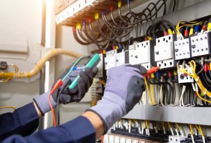
In today’s industrial and commercial facilities, the quality of incoming electrical power is just as important as its availability. Power quality issues like harmonics and phase imbalance are silent efficiency killers. They can cause equipment to overheat, malfunction, and fail prematurely, leading to costly downtime and energy waste.
For electrical maintenance professionals, understanding how to analyze these issues is a critical skill. This guide will walk you through the process of performing a power quality analysis, focusing on two of the most common and damaging disturbances: harmonics and phase imbalance.
What is Power Quality?
Power quality refers to the ability of the electrical system to supply power that is stable, within voltage and frequency tolerances, and free of distortion.
Disturbances in power quality are typically introduced by non-linear loads or system faults, and they can lead to:
· Motor failures: overheating, reduced efficiency, and shortened lifespan.
· Transformer issues: core saturation and overheating.
· Control system malfunctions: erratic behavior due to voltage distortion.
· Computer/electronic failures: crashes, data errors, and hardware damage.
· Increased energy consumption: due to power factor penalties and reduced efficiency.
Understanding Harmonics
What are Harmonics?
Under ideal conditions, the voltage and current waveforms in a power system are pure sine waves at a fundamental frequency (50 or 60 Hz). However, modern electronic devices like variable frequency drives (VFDs), switch-mode power supplies, LED lighting, and arc furnaces draw current in short, non-linear pulses. This behavior distorts the waveform.
These distortions are called harmonics – sinusoidal voltages or currents at frequencies that are integer multiples of the fundamental frequency . For example, on a 60 Hz system, the 5th harmonic has a frequency of 300 Hz, and the 7th harmonic is 420 Hz.
Harmonics combine with the fundamental frequency to create a distorted waveform. The harmonic content is quantified as Total Harmonic Distortion (THD) .
Common Effects of Harmonics
· Transformer Heating: Eddy current and hysteresis losses increase, causing overheating.
· Neutral Overloading: In 3-phase 4-wire systems, triplen harmonics (3rd, 9th, 15th) are additive in the neutral conductor, leading to fires.
· Circuit Breaker Tripping: Nuisance tripping due to distorted current waveforms.
· Telecommunication Interference: Noise induced in nearby communication lines.
Understanding Phase Imbalance
What is Voltage Unbalance?
A perfectly balanced three-phase system has equal voltage magnitudes on all three phases, exactly 120 degrees apart. Voltage unbalance occurs when the three phase voltages differ in magnitude or are not spaced exactly 120 degrees apart .
The Impact of Voltage Unbalance on Motors
Motors are particularly vulnerable to voltage unbalance. The National Electrical Manufacturers Association (NEMA) recommends that voltage unbalance should not exceed 1%. Here’s why:
A 1% voltage unbalance can cause a 6% to 10% current unbalance. The phase with the lowest voltage will draw the highest current, increasing the temperature in that winding . This can drastically reduce insulation life. According to industry data, a 2% voltage unbalance can reduce the expected insulation life of a motor by half .
Calculating Voltage Unbalance
You don’t need specialized equipment for a basic check. You can use a standard multimeter to measure the voltage between each pair of phases. The formula is straightforward :
Percent Voltage Unbalance = (Maximum Deviation from Average Voltage / Average Voltage) × 100%
Example Calculation
· L1-L2 = 471 V
· L1-L3 = 476 V
· L2-L3 = 473 V
- Average: (471 + 476 + 473) / 3 = 473.3 V
- Maximum Deviation from Average:
· 476 – 473.3 = 2.7 V (maximum deviation)
· 473.3 – 471 = 2.3 V - Voltage Unbalance = (2.7 / 473.3) × 100% = 0.57% (This is an acceptable value).
How to Perform a Power Quality Analysis
- Select the Right Instrument
You need a Power Quality Analyzer (PQA) . Most modern analyzers are 3-phase devices that can measure and record voltage, current, harmonics, power, and other parameters over time . When selecting an analyzer, ensure it conforms to relevant standards like IEC 61000-4-30 for measurement methods.
- Plan the Measurement
· Identify the Point of Common Coupling (PCC): This is the point where the customer’s installation connects to the utility grid. It’s typically where compliance with standards like IEEE 519 is evaluated .
· Ensure Safety: Wear appropriate PPE, follow LOTO procedures, and ensure the analyzer’s voltage and current ranges are compatible with the system.
- Connect the Analyzer (Wiring Configuration)
Proper connection is crucial for accurate measurements. The analyzer manual will provide specific wiring diagrams for different system types .
Here are the most common configurations:
· Single-Phase (1P2W): For single-phase loads .
· 3-Phase 4-Wire (3P4W): Standard for Wye (Y) systems. Connect voltage probes to L1, L2, L3, and Neutral (N). You’ll need current clamps on L1, L2, and L3 .
· 3-Phase 3-Wire (3P3W): Used in Delta systems. Connect voltage probes to L1, L2, and L3 without a neutral. Current clamps are usually placed on L1 and L3; the current on L2 is calculated .
- Configure the Analyzer
Set up the analyzer in the configuration menu by inputting:
· Wiring Type: Single-phase, 3-phase 3-wire, or 3-phase 4-wire .
· Current Clamp Types: Specify the type of clamp (e.g., Rogowski coil, CT) and its range.
· Voltage and Current Ratios (VT/CT Ratios): If measuring on medium or high voltage systems through instrument transformers, you must set the correct ratios for scaling .
- Start Recording and Collect Data
Start the data logging function. The duration depends on your goal. For a general baseline, 7 days is often recommended to capture typical operating cycles.
- Analyze the Results
This is where you interpret the data to find problems.
Analyzing Harmonics Against Standards
Analyze the data to get the THD% and the Individual Harmonic Distortion (IHD) . For guidance, the IEEE Standard 519 provides limits for voltage and current harmonics at the PCC .
Recommended IEEE 519 Voltage Distortion Limits (at PCC):
Bus Voltage at PCC (V) Individual Harmonic (%) Total Harmonic Distortion THD (%)
V ≤ 1.0 kV 5.0 8.0
1 kV < V ≤ 69 kV 3.0 5.5
69 kV < V ≤ 161 kV 1.5 2.5
If your THD or specific harmonics exceed the limits from standards like IEEE 519, it indicates a power quality problem that needs mitigation.
Basic Mitigation Strategies
Mitigating Harmonics
· Passive Filters: Tuned to absorb specific harmonic frequencies.
· Active Harmonic Filters: Electronic systems that inject counter-distorting currents to cancel out harmonics.
· Line Reactors: Placed in series with non-linear loads (like VFDs) to smooth out current pulses.
· K-Rated Transformers: Specially designed to handle harmonic heating without derating.
Mitigating Phase Imbalance
· Balancing Single-Phase Loads: Strategically redistribute single-phase loads across all three phases to equalize current draw.
· Use of a 3-Phase Balancing Transformer: Special transformers can be used to correct severe imbalances.
· Check for Utility Supply Issues: If the imbalance is at the PCC, the issue may be on the utility side, requiring them to investigate.
Conclusion
Performing a power quality analysis is a vital skill for modern electrical maintenance. By understanding how to measure, analyze, and interpret data for harmonics and phase imbalance, you can prevent costly equipment failures, extend asset life, and ensure a reliable, efficient electrical system. Always prioritize safety, use the right instrument, and compare your results to established standards like IEEE 519 to drive informed decisions.
Are you experiencing unexplained equipment failures or efficiency losses? A power quality analysis is a great diagnostic tool to get to the root of the problem