


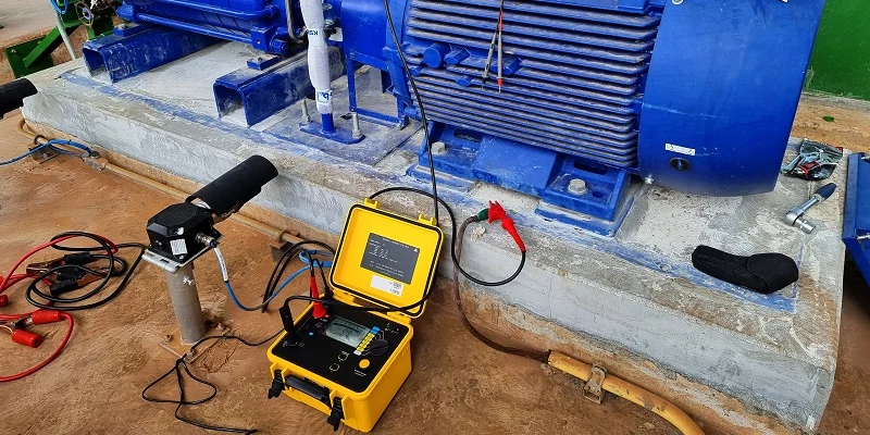
Insulation resistance testing, commonly known as Megger testing, is one of the oldest and most fundamental electrical maintenance procedures. For over a century, it has served as the primary method for verifying the integrity of electrical insulation and preventing catastrophic failures. Whether you are commissioning new equipment, performing routine preventive maintenance, or troubleshooting a fault, understanding how to properly execute and interpret this test is essential for any electrical professional.
This guide provides a comprehensive overview of Megger testing, from its basic principles to step-by-step procedures and interpretation of results.
What is Insulation Resistance Testing?
An insulation resistance test, often referred to by the genericized trademark “Megger” test, measures the resistance of a conductor’s insulating jacket to current leakage. The test works by applying a controlled DC voltage—typically between 500V and 5kV—across the insulation and measuring any leakage current that flows through it.
The fundamental principle is simple: healthy insulation acts as an excellent barrier to current flow, resulting in a very high resistance reading (typically in the megohm or gigohm range). Deteriorated or contaminated insulation allows more current to leak, producing a lower resistance reading. By applying a higher-than-operating voltage, the test stresses the insulation to reveal weaknesses that might not show up during normal operation.
The primary purposes of the test include:
- Pre-Commissioning: Verifying the integrity of new installations before energizing them.
- Preventive Maintenance: Detecting gradual degradation due to aging, moisture, or contamination to plan maintenance activities.
- Troubleshooting: Identifying the source of faults in malfunctioning equipment.
- Post-Repair Verification: Confirming the quality of repairs or reconditioning work.
NFPA 70B, the standard for electrical equipment maintenance, explicitly references insulation resistance quality as a fundamental test in its Chapter 7, underscoring its importance in any structured maintenance program.
Selecting the Correct Test Voltage
Choosing the correct test voltage is critical. Using a voltage that is too high can damage the insulation, while a voltage that is too low may not reveal weaknesses. General guidelines, based on standards like IEEE 43, recommend the following:
| Equipment Rated Voltage | Recommended Test Voltage (DC) |
|---|---|
| Less than 1000V | 500V |
| 1000V – 2500V | 500V – 1000V |
| 2501V – 5000V | 1000V – 2500V |
| 5001V – 12,000V | 2500V – 5000V |
| Greater than 12,000V | 5000V – 10,000V |
A common rule of thumb for motors is to select the next standard voltage step above the equipment’s rated circuit voltage. For instance, a 480V system is typically tested at 1000V. Always consult the manufacturer’s instructions and relevant safety standards before proceeding.
Step-by-Step Testing Procedure
Following a consistent and safe procedure is vital for accurate results and personnel safety. The process generally involves these steps:
1. Preparation and Safety First
- De-Energize and Isolate: The equipment under test must be completely de-energized and disconnected from all power sources. Confirm a zero-energy state using a voltage tester and apply Lockout/Tagout (LOTO) procedures.
- Discharge Capacitance: Large equipment (motors, transformers, long cables) can hold a dangerous charge. It must be discharged before testing to prevent shock or damage to the tester. The equipment should also be discharged immediately after testing, before handling leads.
- Clean the Equipment: Dirt, moisture, and oil on the surface can create leakage paths and cause false readings. Clean the test area as needed.
2. Set Up and Connect the Tester
- Select the Test Voltage: Set your insulation resistance tester (e.g., a Fluke 1587) to the appropriate voltage determined in the previous section.
- Verify Tester Operation: Perform open and short circuit checks before connecting to the equipment to ensure the tester is functioning correctly. Use a known “proving unit” or connect the leads together and verify zero resistance, and then separate them to verify the maximum reading.
- Make the Connections: Connect the tester leads to the conductors being tested. Typical test connections include:
- Phase-to-Ground: One lead to a phase conductor, the other to the equipment grounding conductor or the equipment frame.
- Phase-to-Phase: One lead to one phase, the other to a different phase to check insulation between conductors.
- Winding-to-Ground: For motors and transformers, test each winding separately against the grounded frame.
3. Perform the Test and Record Data
- Press and Hold: Activate the tester’s “TEST” button and hold it.
- Wait for Stabilization: Allow the reading to stabilize. This may take up to 60 seconds, especially for larger, capacitive equipment. For the standard one-minute test, record the value at exactly 60 seconds after the test voltage has been applied.
- Record Conditions: Document the resistance reading along with the ambient temperature and humidity. These environmental factors have a significant impact on insulation resistance and are essential for trend analysis.
Interpreting Results: What Do the Numbers Mean?
A single insulation resistance reading is not enough to make a judgment. It must be compared against standards, manufacturer data, and historical baselines.
Minimum Acceptable Values
A common industry rule of thumb is that a reading above 1 Megohm (MΩ) is considered “good” for most general applications. However, this is a minimum standard.
More specific guidelines from IEEE 43 for motors and generators, corrected to a winding temperature of 40°C, are often used:
- For most random-wound or form-wound coils rated below 1kV: Minimum IR is 5 MΩ.
- For most DC armatures and AC windings built after about 1970, the minimum IR is 100 MΩ.
- For older windings and other types not described above: Minimum IR is kV + 1 (e.g., for a 4kV motor, minimum is 5 MΩ).
If a reading falls below these minimums, the equipment should not be energized until corrective measures (like cleaning and baking) are taken.
Advanced Measurements: DAR and PI
For a more nuanced assessment, especially on large, high-capacitance equipment, two additional calculations are used:
- Dielectric Absorption Ratio (DAR): The ratio of a 60-second reading to a 30-second reading (R60/R30). A DAR of 1.25 or greater generally indicates acceptable insulation, while a ratio lower than 1.0 is a sign of trouble.
- Polarization Index (PI): The ratio of a 10-minute reading to a 1-minute reading (R10/R1). A PI of 2.0 or higher is considered good, while a value of 1.5 or lower suggests the insulation is contaminated or has absorbed moisture. PI values are most meaningful when trending insulation for motors and generators.
Common Mistakes to Avoid
To ensure accurate and safe testing, avoid these common pitfalls:
- Testing Live Equipment: This is a severe safety hazard that can lead to injury, death, or equipment damage. Always de-energize and verify a zero-energy state before connecting the tester.
- Incorrect Test Voltage: Applying a test voltage that is too low may miss flaws, while a voltage that is too high can damage sound insulation.
- Ignoring Temperature and Humidity: Readings can vary significantly with environmental conditions. Always record these factors for a valid comparison.
- Failing to Discharge: Not discharging the equipment before and after testing can be dangerous and damage the tester.
- Rushing the Test: For large equipment, readings can take time to stabilize. Cutting the test short can yield inaccurate results.
- Not Documenting Results: Without a historical record to compare against, a reading in the megohm range is essentially meaningless for trending the health of the insulation.
Conclusion
Insulation resistance testing is a cornerstone of preventive electrical maintenance. By understanding the principles, following a rigorous and safe procedure, and correctly interpreting the results, maintenance professionals can identify impending failures before they cause costly downtime or dangerous events.
The key takeaway is to record and compare your results over time. A single good reading is a snapshot; a series of consistent readings is a testament to the health of your equipment. Always prioritize safety, adhere to standards like NFPA 70B and IEEE 43, and integrate Megger testing as a routine part of your maintenance program